UQ St Lucia Stereo Vehicular Dataset #
Introduction #
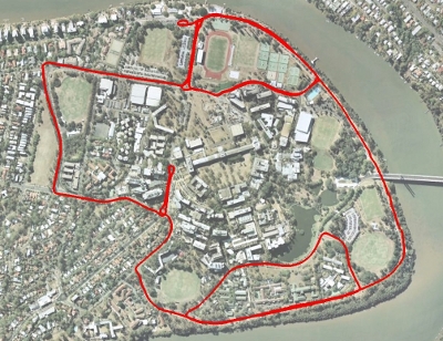
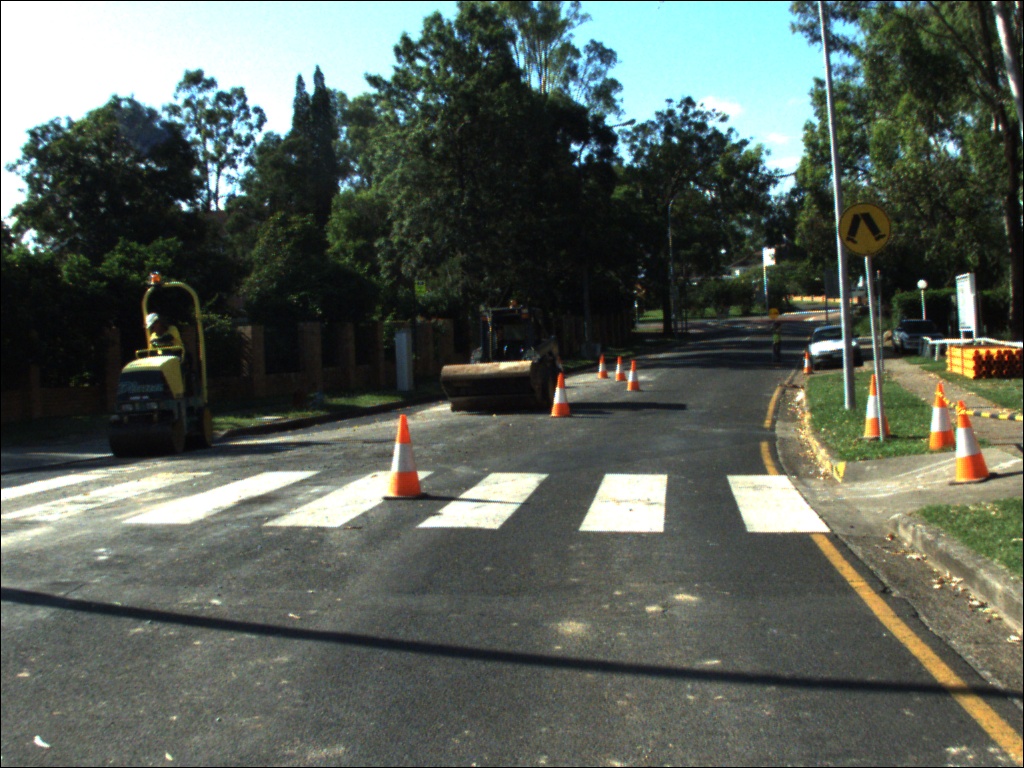
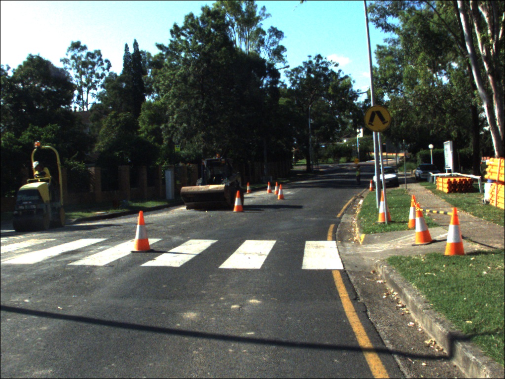
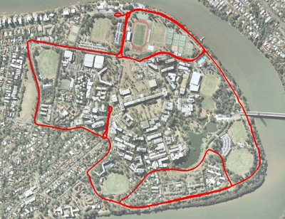
The UQ St Lucia Dataset is a vision dataset gathered from a car driven in a 9.5km circuit around the University of Queensland’s St Lucia campus on 15th December 2010. The data consists of visual data from a calibrated stereo camera pair, translation and orientation information as a ground truth from an XSens Mti-g INS/GPS and additional information from a USB NMEA GPS. The dataset traverses local roads and encounters a number of varying scenarios including roadworks, speed bumps, bright scenes, dark scenes, reverse traverses, a number of loop closure events, multi-lane roads, roundabouts and speeds of up to 60 km/h. See below for a video of the full-trajectory from both stereo cameras:
This dataset has been released for free and public use in testing and evaluating stereo visual odometry and visual SLAM algorithms.
If you use this dataset in your own work we request that you cite our paper: Unaided Stereo Vision Based Pose Estimation (Bib, Ris, XML/EndNote) in your bibliography.
@inproceedings{Warren2010,
address = {Brisbane},
author = {Warren, Michael and McKinnon, D. and He, H. and Upcroft, Ben},
booktitle = {Australasian Conference on Robotics and Automation},
editor = {Wyeth, Gordon and Upcroft, Ben},
keywords = {Stereo vision,computer vision,dataset,field robotics,visual odometry},
mendeley-tags = {computer vision,field robotics,visual odometry},
publisher = {Australian Robotics and Automation Association},
title = {{Unaided stereo vision based pose estimation}},
url = {http://eprints.qut.edu.au/39881/},
year = {2010}
}
Need some help? Follow the Getting Started guide below!
Dataset #
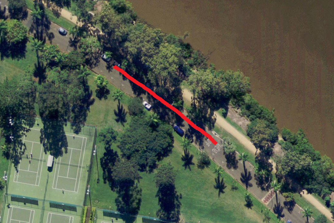
Links are provided to the images and other logs below. The full set of images is available as separated 2GiB RAR files, but because of its size a smaller subset of 100 images in both raw and debayered/undistorted formats is also available for evaluation. MD5 Checksums are provided on large files to ensure integrity of downloaded data.
 100 Frame Subset (Frames 1500 to 1600) 100 Frame Subset (Frames 1500 to 1600) | ||
|---|---|---|
| Stereo Image Data | Log Data | |
| See full dataset log below. | |
 Full UQ St Lucia Dataset Full UQ St Lucia Dataset | ||
| Stereo Image Data | Log Data | |
|
| |
Sensor/Dataset Details #
Sensor | Stereo Vision Rig | XSens MTi-G | USB NMEA GPS |
|---|---|---|---|
Details |
|
|
|
Update Frequency | 30 fps (125uS resolution) | 120 Hz | 1 Hz |
Number of Logged Items | 33196 | 132799 | 1103 |
Calibration #
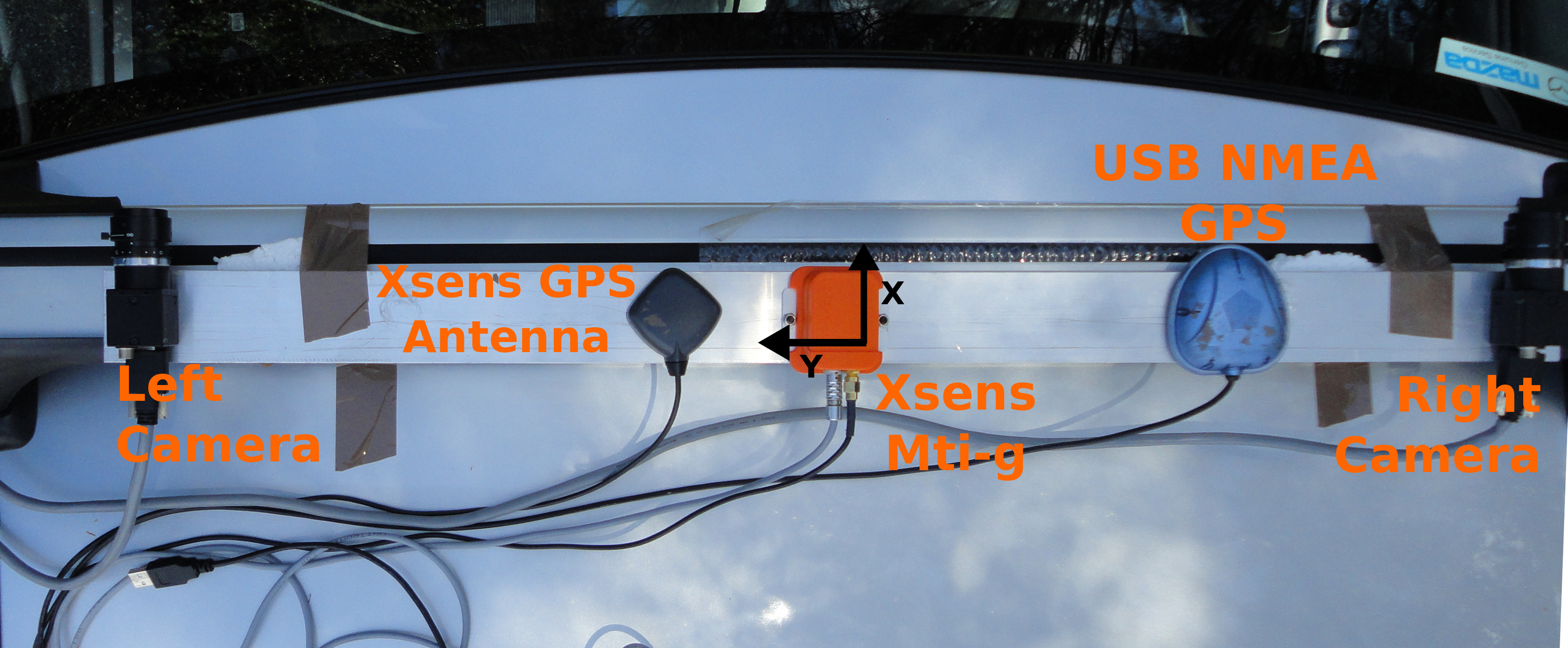
For ease of transformations, the body co-ordinate system origin is set at the centre of the XSens Mti-g. These locations are accurate to within approximately 10mm. Defined position of GPS antennas is in the centre of the sensor. See the layout image below for clarification.
Sensor | Left Camera | Right Camera | XSens Mti-g | Xsens GPS | NMEA GPS |
|---|---|---|---|---|---|
Position,t (x,y,z) (m) | 0.0, 0.379, 0.0 | 0.0, -0.371, 0.0 | 0.0, 0.0, 0.0 | 0.01, 0.1, 0.0 | 0.01, 0.2, 0.0 |
Euler rotations (format RxRyRz) (radians) | 0.0, 0.0, 0.0 | 0.0, 0.0, 0.0 | 0.0, 0.0, 0.0 | 0.0, 0.0, 0.0 | 0.0, 0.0, 0.0 |
Monocular and Stereo Camera Calibration #
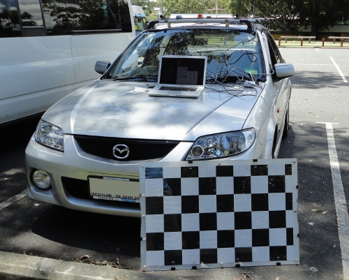
The stereo calibration has been completed using more than 150 checkerboard image pairs taken using the stereo rig while placed on the vehicle. Using our AMCC Toolbox (an extension of the RADDOC Toolbox and Bouget's Camera Calibration Toolbox for Matlab), we have calibrated the stereo pair using the checkboard images given below in Calibration Data.
Intrinsic Calibration Parameters #
Camera | Focal Length X,Y (pixels) | Principle Point (x,y) (pixels) | Distortions (K1,K2,P1,P2,K3) |
|---|---|---|---|
Left | 1246.56167, 1247.09234 | 532.28794, 383.60407 | -0.32598, 0.18151, 0.00033, -0.00045, 0.00000 |
Right | 1244.80505, 1245.81569 | 506.63554, 390.70481 | -0.32512, 0.17124, 0.00003, 0.00003, 0.00000 |
Extrinsic Calibration Parameters #
The rotation and translation transform between the stereo pair. Left camera is at the origin. The camera co-ordinate system is defined as follows: X left, Y up, Z forward.
Translation, t (x, y, z, in mm) | Euler rotations (format RxRyRz) (radians) | Rotation matrix |
|---|---|---|
-750.66669, -3.85768, 3.09594 | -0.00515, -0.00531, -0.00134 | [0.999985020769994, 0.001356661749366, -0.005302612991045 |
Calibration Data #
The data used to calibrate the stereo dataset is provided here for your convenience if you would like to perform your own calibration. The stereo images containing multiple views of a checkerboard are provided in 101215_151454_MultiCamera0_calibration.rar.
If you would like to use our calibration you can download the monocular and stereo calibration files here that are compatible with Bouget's Camera Calibration for Matlab. If you wish to use OpenCV or our multicamera_data_player app (see below) to undistort the imagery, we have provided convenient XMLs with the data that OpenCV can import directly.
Data Type | Left Camera | Right Camera | Stereo Pair |
|---|---|---|---|
Images |
|
| |
Matlab Calibration Results Files | |||
OpenCV Intrinsics Files | |||
OpenCV Distortion Files |
Log File Format #
GPS #
Data Type | Timestamp (seconds) | Timestamp (millsec) | UTC Time Hours | UTC Time Minutes | UTC Time Second | Latitude (deg) | Longitude (deg) | Altitude (deg) | Horizontal Position Error | Vertical Position Error | Heading | Speed (m/s) | Climb rate (m/s) | Satellites | Observations on L1 | Observations on L2 | Position Type | Geoidal Seperation |
|---|---|---|---|---|---|---|---|---|---|---|---|---|---|---|---|---|---|---|
Example | 1292391531 | 313628 | 0 | 0 | 0.000000 | -27.492 | 153.011 | 42.78900 | 7.01850 | 0.00 | 0.00 | 0.00 | 0.00 | 0 | 0 | 0 | 1 | 0.00000 |
INS #
Data Type | Timestamp (seconds) | Timestamp (millisec) | Latitude (deg) | Longitude (deg) | Altitude (m) | Height AMSL (m) | Velocity East North Up [vENU] X (m/s) | Velocity East North Up [vENU] Y (m/s) | Velocity East North Up [vENU] Z (m/s) | Roll (rad) | Pitch (rad) | Yaw (rad) |
|---|---|---|---|---|---|---|---|---|---|---|---|---|
Example | 1292391532 | 94359 | -27.492 | 153.011 | 43.187 | 43.187 | -0.189 | -0.018 | 0.318 | 0.014 | -0.026 | 1.282561681 |
IMU #
Data Type | Timestamp (seconds) | Timestamp (milliseconds) | X Acceleration (m/s^2) | Y Acceleration (m/s^2) | Z Acceleration (m/s^2) | Gyro X Velocity (rad/s) | Gyro Y Velocity (rad/s) | Gyro Z Velocity (rad/s) |
|---|---|---|---|---|---|---|---|---|
Example | 1292391532 | 94299 | -0.164379 | 0.129229 | -9.68359 | -0.00312483 | -0.00254386 | -0.00429477 |
MultiCamera #
First Line (where columns 2-22 are repeated for each camera):
Data Type | Total Number of Cameras | Cam 0 Expected Image Width (pixels) | Cam 0 Expected Image Height (pixels) | Cam 0 Data format | Cam 0 Frame Rate (Hz) | Cam 0 X offset (m) | Cam 0 Y offset (m) | Cam 0 Z offset (m) | Cam 0 Roll offset (rad) | Cam 0 Pitch offset (rad) | Cam 0 Yaw offset (rad) |
| Cam 0 Focal Length Fx (pixels) | Cam 0 Focal Length Fy (pixels) | Cam 0 Principle Point cx (pixels) | Cam 0 Principle Point cy (pixels) | Cam 0 k1 | Cam 0 k2 | Cam 0 p1 | Cam 0 p2 | Cam 1 Expected Image Width (pix) | Cam 1 Expected Image Height (pix) | Cam 1 Data format | Cam 1 Frame Rate (Hz) | Cam 1 X offset (m) | Cam 1 Y offset (m) | Cam 1 Z offset (m) | Cam 1 Roll offset (rad) | Cam 1 Pitch offset (rad) | Cam 1 Yaw offset (rad) |
| Cam 1 Focal Length Fx (pix) | Cam 1 Focal Length Fy (pix) | Cam 1 Principle Point cx (pix) | Cam 1 Principle Point cy (pix) | Cam 1 k1 | Cam 1 k2 | Cam 1 p1 | Cam 1 p2 |
|---|---|---|---|---|---|---|---|---|---|---|---|---|---|---|---|---|---|---|---|---|---|---|---|---|---|---|---|---|---|---|---|---|---|---|---|---|---|---|---|
Example | 2 | 1024 | 768 | GRAY8 | 30 | 0 | 0.379 | 0 | 0 | 0 | 0 | 0 0 0 | 0 | 0 | 0 | 0 | 0 | 0 | 0 | 0 | 1024 | 768 | GRAY8 | 30 | 0 | -0.371 | 0 | 0 | 0 | 0 | 0 0 0 | 0 | 0 | 0 | 0 | 0 | 0 | 0 | 0 |
All subsequent lines. Columns 3-5 are repeated for each camera and column 6 is repeated afterwards:
Data Type | Cam 0 Timestamp (seconds) | Cam 0 Timestamp (millisec) | Cam 0 Image Width (pixels) | Cam 0 Image Height (pixels) | Cam 0 Data format | Cam 1 Timestamp (seconds) | Cam 1 Timestamp (millisec) | Cam 1 Image Width (pix) | Cam 1 Image Height (pix) | Cam 1 Data format | Cam 0 Relative Image Location and Name | Cam 1 Relative Image Location and Name |
|---|---|---|---|---|---|---|---|---|---|---|---|---|
Example | 1292391532 | 101549 | 1024 | 768 | GRAY8 | 1292391532 | 101521 | 1024 | 768 | GRAY8 | .//101215_153851_MultiCamera0//cam0_image00001.bmp | .//101215_153851_MultiCamera0//cam1_image00001.bmp |
Getting Started #
- Download the 101215_153851_MultiCamera0_subset_db.rar file. This contains a small subset of processed data from the dataset (‘db’ = ‘debayered’). Extract and examine the imagery to see if it suits your purposes.
- Download the 101215_153851_MultiCamera0_subset.rar file. This contains the same small subset as in the full size dataset, but the images are in their raw form. This allows you to experiment with your own image processing and do some experimental evaluation before committing to downloading the whole dataset.
- Extract 101215_153851_MultiCamera0_subset.rar using WinRAR on Windows or your favourite package unzipper in Linux. These should uncompress into a single folder titled 101215_153851_MultiCamera0_subset. Keep a note of the path of this folder.
- The images provided in the subset and larger whole dataset require some post-processing before they are useful. Firstly, the images are in a bayer format, which means that they appear as a speckled greyscale image. However, colour information is encapsulated within the image encoding, and can be extracted using a software package such as OpenCV. The images also have not yet been undistorted nor rectified. The following steps allow you to debayer, undistort and rectify the images according to your needs with a single executable.
- Download MultiCameraDataPlayer (or its source and dependencies, then build the application).
- Download the intrinsics and distortion xml files for the data (see Calibration)
- Place all four intrinsics and data files in a single folder called intrinsics or something similar. Keep a note of the path of this folder.
- Run MultiCameraDataPlayer using the examples provided on it’s download page as guidance. For most purposes you will want to debayer and undistort the imagery and export to a video file format for ease of use.
- Finished! Now run your visual odometry algorithm on the processed dataset.
When you are satisfied with the quality of the evaluation set, download all 19 .RAR files (see Dataset) containing the images. These are compressed in sizes of just under 2GB to fit browser size limitations. Extract the files as a group using WinRAR on Windows or your favourite package unzipper in Linux. These should uncompress into a single folder titled 101215_153851_MultiCamera0. Keep a note of the path of this folder. Run MultiCameraDataPlayer on the sequence you wish to evaluate and process for use in your visual odometry software.
Additional information #
Orca Playback #
The data has been recorded using the Orca Robotics package. Placing all the log files in the same directory as the 101215_153851_MultiCamera0 directory and calling Orca’s logplayer on the data will allow you to playback and re-export the data as you see fit.
Timestamping #
- Images are timestamped at the point of entry to the DMA buffer, this means that the timestamps will vary slightly but are guaranteed to be synchronised within 125 uS of each other as specified by the firewire protocol.
- Timestamps for the Ins0, Gps0 and Imu0 logs are transferred from the Xsens according to GPS UTC time.
- Timestamps for the Gps1 log is transferred from the NMEA GPS according to GPS UTC time.
- The system used to record data is non real-time, using the internal system clock, therefore timestamping may be inacurrate. We generally assume that timestamps are accurate within at least 100mS, often better.
Credits #
Michael Warren, Ben Upcroft and Michael Shiel all contributed to the production of this dataset.
Queries #
Please use the following form for dataset queries:
